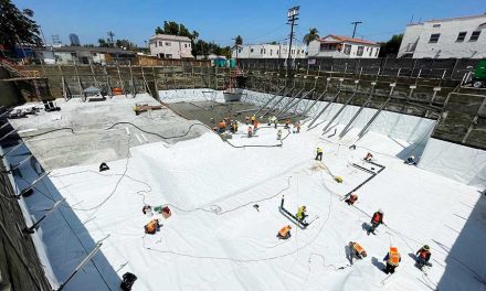
New electronic leak detection methods can locate even the smallest leaks with pinpoint accuracy on both vertical and horizontal surfaces
For almost two decades, electronic leak detection (ELD) has been used in North America to test for leaks in new and existing roofs. There are at least three different methods of ELD, but all use the same basic principle: using electrical current to precisely locate membrane breaches.
ELD offers a host of advantages over other methods. Alternatives such as infrared thermography, nuclear moisture testing, and electrical impedance testing actually test for moisture, so they don’t detect a problem until water has already built up under the membrane and damage has been done. Second, because they test only for moisture, they don’t reveal the actual location of the leak. That work must be done separately—often on hands and knees.
ELD, on the other hand, can test nearly all roof systems, new or old, wet or dry, and can pinpoint the actual leak, even if it’s too small to be seen easily. Systems are available that monitor for leaks continuously, with real-time alerts to building managers.
Recent advances have made it possible to test semi-conductive membranes, such as cold fluid-applied membranes and dark EDPM. Electronic leak detection has proven so effective that many roof membrane manufacturers now accept or require ELD as an integrity test before issuing a warranty for newly installed materials.
Until recently, though, there was no industry-wide standard for electronic leak detection. About ten years ago, ASTM International began putting together guidelines. This guideline was published a few years later as D-7877-14 Standard Guide for Electronic Methods for Detecting and Locating Leaks in Waterproof Membranes.
The 2014 publication described four different approaches to ELD, guidelines for each testing method, and outlined what each testing method can deliver along with its limitations. It also covered the requirements for a valid test. Each testing method’s requirements, oper-ation, and limitations are described.
Low voltage and high voltage testing methods have the same basic requirements. These requirements include (1) a conductive substrate directly below the membrane, (2) the membrane must be exposed, (3) there must be a ground connection, and (4) there must be an electrical path to ground.
Last summer—in July of 2019—ASTM finally published the first industry-wide standard on electronic leak detection for roofs as D-8231-19 Standard Practice for the Use of a Low Voltage Electronic Scanning System for Detecting and Locating Breaches in Roofing and Waterproofing Membranes.
Pat Vokey, vice president of Detec Systems, explains, “The new Standard Practice D-8231 expands on the scanning platform method described in ASTM D-7877 Standard Guide. D-8231 creates a detail oriented solution for ELD, dedicated to the scanning platform with two important additions. D-8231 also states that membrane testing must be performed before overburden is installed to ensure accurate results.”
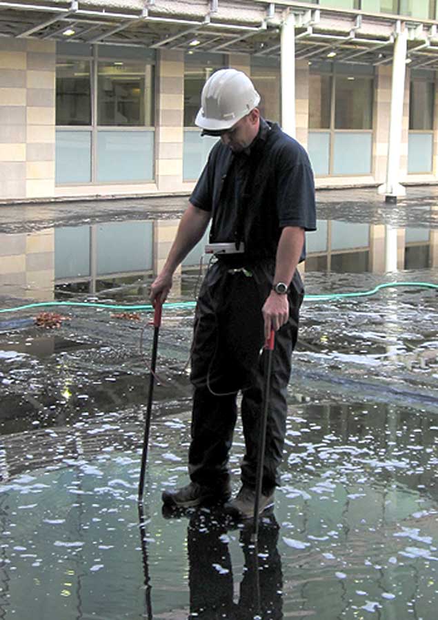
Low-voltage vector mapping locates potential leaks using a pair of specialized probes resembling ski poles.
Both publications are available through the ASTM website in PDF or hard copy for $50.
Vokey says. “Although work is being done to educate the participants on the physics of ELD testing, the industry is still in the dark. Many architectural specifications are inadequate, unclear, or outdated. Conventional roof assemblies require a conductive medium directly under the membrane for valid testing. Often, specifications do not include any conductive medium.”
“Inaccurate unscientific claims made by testing agencies also contribute to the confusion,” she continues. “Educating all stakeholders on the physics behind ELD is the first step toward clarifying any myths and false information”.
The Basics
The key to all ELD methods is that water conducts electricity very well—at least 10 times as well as most roofing membranes. ELD requires a conductive roof substrate directly below a non-conductive membrane. If the deck is wooden, or the membrane is conductive (such as black EPDM) the assembly will typically not be testable. (Although recent advances have made it possible to overcome this difficulty, explained later in this story.)
To test the membrane, an electrical field is formed immediately above and below the membrane. If a short occurs between the two, the leak can be pinpointed, repaired, and roof re-tested.
Method 1: Low Voltage Vector Mapping
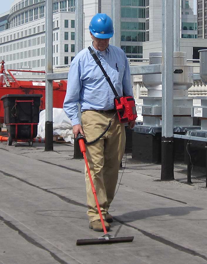
The low-voltage testing method—technically “low-voltage fault current testing”— is perhaps the most common. Popularized by International Leak Detection, which trade-named the system Electric Field Vector Mapping (EFVM), it involves wetting the top of the membrane to create an upper electrical “plate”. The structural deck acts as the lower electrical plate, and the roof membrane located in between acts as the insulator. Any leak in the membrane will create an electric short between the upper and lower “plates,” and by using specialized probes—which superficially resemble ski poles— the technician can determine the direction of the current and the location of the leak. Additional readings verify the exact location of the defect.
The system does have a few limitations. Low-voltage vector mapping requires a conductive wire to be laid around the area being tested—usually the entire roof perimeter—to electrify the top plate. Any through-roof penetrations, such as drains and HVAC equipment, must be electrically isolated from the field by also encircling them with wire.
Some operators claim it is possible to test the membrane underlying ballasted and green roofs without removing the overburden, which often contains enough moisture that wetting the roof isn’t even necessary. However, the new ASTM Standard D-8231-19 states that testing through overburden is “non-conclusive,” and reports that the best practice is to test before the overburden is installed, or to remove the overburden prior to testing. The exact wording in section 4.1 is, “Roof designs incorporating a waterproof membrane under overburden must be tested for breaches before overburden is installed.”
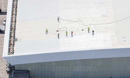
Method 2: High-Voltage
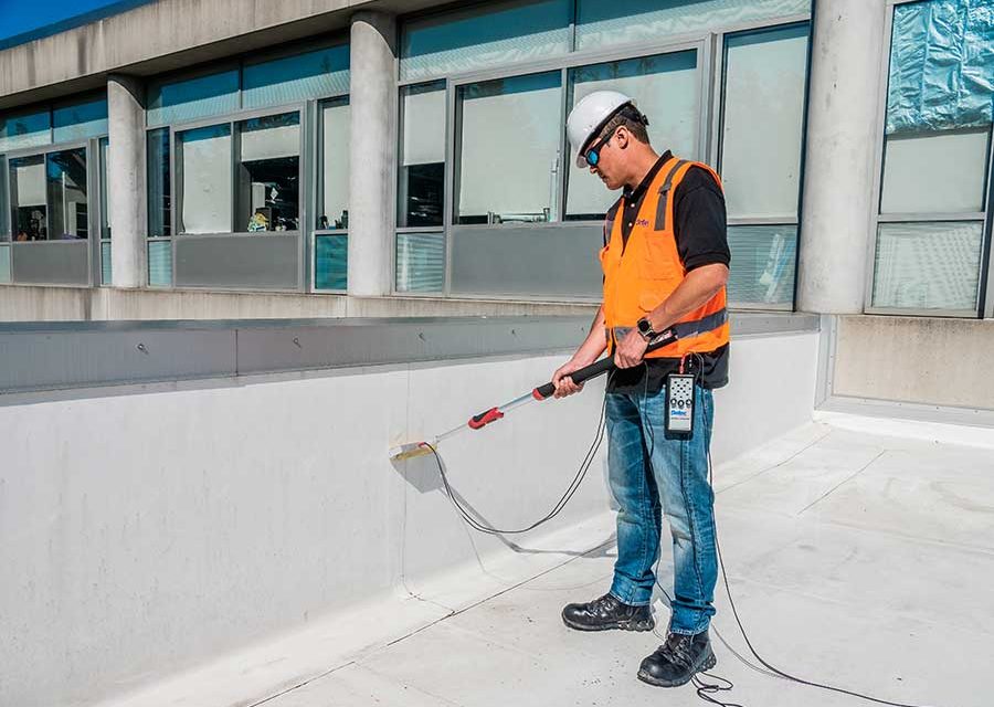
The high voltage method uses relatively high voltage but low amperage, so it’s still relatively safe. It requires a membrane that is perfectly dry and completely exposed. One electrical lead is connected to the roof deck, and the other is attached to a device resembling a push broom with copper bristles. As the operator “sweeps” the surface of the membrane, any moisture or breach in the membrane will allow one of the conductive bristles to complete the circuit between the measuring device and the roof deck.
High voltage testing uses a device resembling a broom with copper bristles, and requires a dry membrane.
Unlike EFVM, high voltage testing can be adapted to vertical surfaces. Instead of a large, broom-like apparatus, the technician uses a smaller brush-like device on vertical surfaces. In either case, the technology is the same.
Like the low-voltage described earlier, this high-voltage method also requires the structural roof deck to be conductive (either metal or concrete) and the membrane to be an insulator. The membrane must also be completely accessible.
As might be expected, the high-voltage method is popular for flat roofs in dry climates with exposed membranes. (For a more in-depth look at this topic, see “Electronic Leak Detection: High vs. Low Voltage” in the Fall 2013 issue.)
Method 3: Low-Voltage Integriscan
Detec Systems has developed and patented a third testing method, which they call “Integriscan.”
It’s a low-voltage system, but unlike vector mapping, IntegriScan tests 100% of the waterproofing/roofing membrane without requiring a perimeter wire or isolating each grounded penetration. Additionally IntegriScan technology can pinpoint breaches in vertical surfaces using a belt mounted roller apparatus.
Like the high-voltage method, it requires the membrane to be exposed. Detec’s website states, “Detec Systems has determined that results are unreliable for testing through over four inches of overburden due to limitations such as… there must be a continuous water path on top of the membrane. Breaches will be missed if there is a gap in water coverage. Drain mat, root barrier and insulation are electrical insulators, disrupting the electrical signal from the top of the overburden. A conductive path must be present from the top of the overburden, through the electrically insulating materials to the saturated membrane. There is a high probability of false negatives due to all the potential breaks in the electrical circuit.”
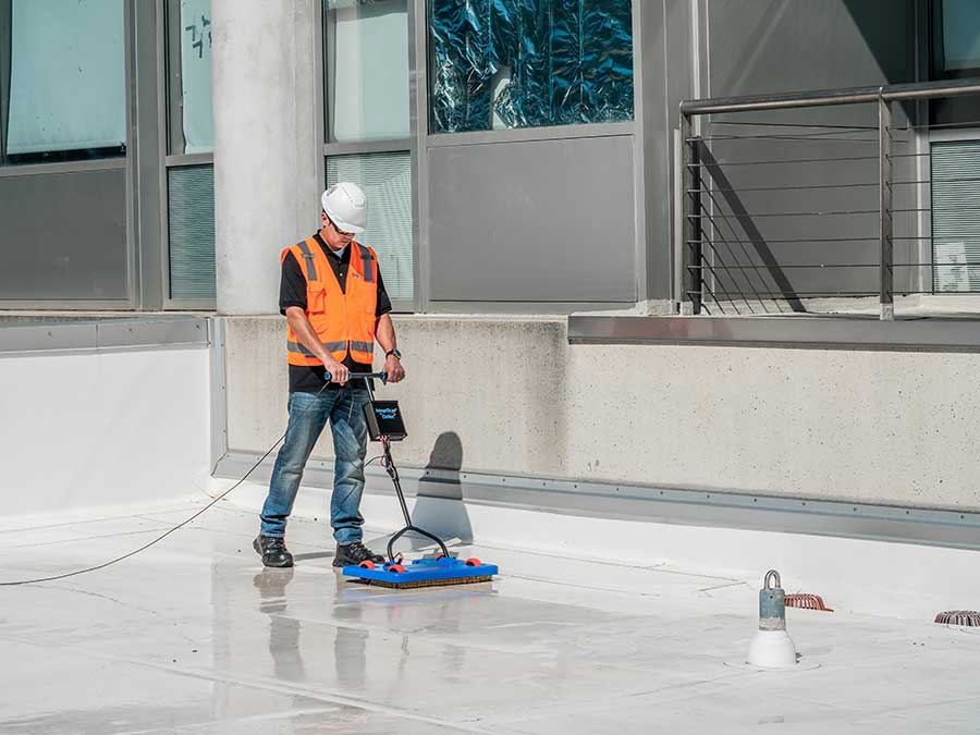
Integriscan uses a wheeled apparatus to test for leaks.
Integriscan can work with a damp membrane. In fact, it requires it. The testing apparatus is mounted on a small, wheeled cart, and the machine scans for shorts in the electrical path to ground between the wet area beneath the machine and the conductive substrate.
Solutions for Non-Conductive Substrates
For years, one of the major shortcomings of all ELD methods is that they all required conductive substrate directly below a non-conductive roof membrane, so wooden decks, or inverted roof systems (with the insulation between the substrate and membrane) were untestable.
To solve the problem of non-conductive roof decks, several companies market a conductive glass felt that can be embedded under or between layers of roof membrane as it is being installed. This “detection membrane” makes it easy to check for leaks on a regular schedule.
Another solution is TruGround primer, which uses carbon black as the conductive ingredient. This conductive primer can be rolled or spray applied just like paint to any non-conductive substrate. It dries in 30 minutes or less. The membrane goes on top, and the result is a roof system that can be tested using the Integriscan method for the life of the roof.
Vokey says that with TruGround, now even semi-conductive membranes are testable. “When black EPDM is placed directly over the TruGround conductive primer, the EPDM can be tested with our scanning technology and future leaks can be pinpointed,” she says. “This is UL listed and FM approved with more than 3,000 membranes and substrates. It is approved by most of the major membrane companies, and has been tested to meet wind uplift standards too.”
The new ASTM Standard D-8231-19 has been updated with instructions on how to scan for leaks on semi-conductive membrane using this approach.
Continuous Monitoring
With recent advances in technology, it’s possible to install a permanent moisture monitoring system that provides automated, constant real-time moisture monitoring for the life of the building. This is especially important for museums, server farms, hospitals, and other buildings where water damage would have catastrophic consequences.
One solution, dubbed Permascan, uses a grid system laid out on the roof substrate with conductive sensor tape. For most jobs, the grid is typically 15 feet square, but could be as small as three feet. This grid is integrated into a permanently embedded monitored system. This system works with both conventional and inverted roofs.
Usually, the leak detection company monitors the roof 24/7. If for security reasons, that’s not desirable, the building owner can self-monitor the system.
Spring 2020 Back Issue
$4.95
Options for Structural Repair
Joints and Waterstops
Electronic Leak Detection
Case Study: Shoshone Power Plant
AVAILABLE AS DIGITAL DOWNLOAD ONLY
Description
Description
Options for Structural Repair
Residential foundation repair is an urgent, growing, and profitable opportunity for waterproofers. Solutions can include piering, grouting, crack injection, and carbon fiber.
Joints and Waterstops
Available in a variety of profiles and materials, waterstops can play a major role in preventing water leakage at cold joints and expansion joints in concrete.
Electronic Leak Detection
New electronic leak detection methods can locate even the smallest leaks with pinpoint accuracy. Some systems can even monitor for leaks continuously with real-time alerts.
Case Study: Shoshone Power Plant
When a century-old hydroelectric plant deep in a Wyoming canyon was re-roofed, it included technology to ensure electronic leak detection even through the EPDM membrane.
Additional Info
Additional information
| Magazine Format | Digital Download Magazine, Print Mailed Magazine |
|---|
Related products