By David Webster, PE, SE, Ph.D
Photos courtesy of David Webster

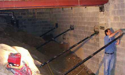
Over the last several years, hydrophilic crystalizing admixtures (HCAs) have emerged as an alternative to traditional waterproofing membranes as the primary waterproofing system in the construction of below-grade concrete basement structures. These products are typically added to the concrete mix at batching and can self-heal through-thickness concrete cracks up to a width of around 0.5mm, sometimes more. This short article was prompted by an examination I conducted in 2020 of a Seattle region mixed-use building constructed in 2018.
The subject building sits atop a gently sloping site and has a roughly square plan with a footprint of approximately 66,000 square feet. It has six levels of wood-framed residential apartments above concrete-framed parking that extends from a single below-grade level to the third level. The lowest parking level is approximately 14 feet below the exterior grade and 4.5 feet below the design water table elevation.
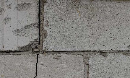
The building was designed as a “reverse bathtub,” in that groundwater was kept out of the basement via a continuous external waterproofing system. Late in the design phase, the traditional exterior waterproofing membrane was replaced with an HCA. The structural slab-on-ground (SOG) was adequately designed for uplift forces caused by hydrostatic pressure from groundwater. However, the provision of adequate strength does not necessarily provide good crack control, and the slab experienced significant cracking, exceeding 1/8-inch in some locations.
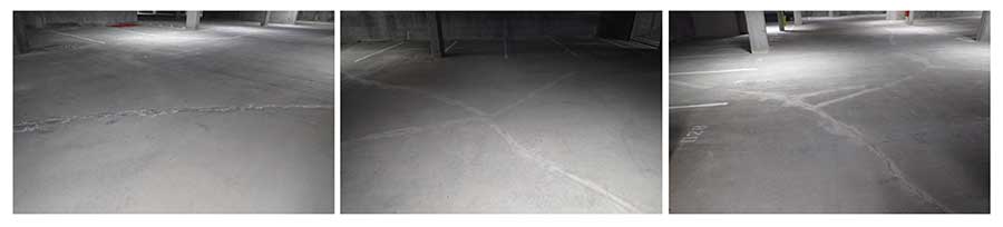
Repaired slab-on-grade (SOG) cracks, above and top, taken at the parking garage property.
Although some HCAs provide a degree of shrinkage reduction, no dedicated shrinkage reducing or compensating product was added to the concrete mix, nor were the reinforcing quantities adjusted. After an extended period of heavy rain, water infiltrated the underground parking levels through some of these cracks.
This article is not a critique of different HCA products, nor is it critical of these as a viable alternative waterproofing system. It focuses instead on the influence the reinforcing ratio (the ratio of the reinforcing cross-sectional area to that of the concrete) has on concrete crack width — specifically due to restrained shrinkage — and how this is typically not a consideration in conventional design.
Concrete Strength and Behavior
Conventional concrete is an inherently brittle material. It is strong in compression but relatively weak in tension. The tensile strength of concrete is typically not utilized in structural concrete design. It is expected that steel-reinforced concrete structures will crack when in service, but this is usually not a problem provided the cracks are not too wide or they result in excessive deflection or corrosion of the reinforcing.
Crack widths can be reduced by increasing the quantity of reinforcing, reducing bar spacing, and by careful detailing. They may also be reduced by additives to the concrete mix design that reduce or compensate for shrinkage, the placement of movement joints and pour-back strips, and by careful curing.
Cracking occurs when the concrete is in tension and the tensile stress exceeds the tensile rupture strength of the concrete. The tensile rupture strength of concrete is typically only 7% to 10% of the compressive strength, but both the compressive and tensile strengths vary with concrete age after placement. Tensile stresses may be caused by the application of external loads (e.g., self-weight, live load, wind, or earthquake loads, etc). They may also occur when thermal contraction or concrete shrinkage is prevented.
In the case of shrinkage, this happens as the concrete tries to shrink, but it is prevented from doing so. This is called restrained shrinkage. The focus in this article is on the relationship between restrained shrinkage and the reinforcing ratio.
Concrete Shrinkage
Over the life of the structure, concrete will volumetrically shrink as it dries and cures. The process takes many years, but the majority of this shrinkage will occur in the first few weeks. The total long-term (ultimate) shrinkage may be as little as 0.02% or as high as 0.11%, but is more often in the range 0.05% to 0.08%. If this shrinkage is restrained, tensile stresses will develop in the concrete that may exceed its tensile rupture strength, at which point the concrete will crack.
Some of the concrete tensile stresses induced by restrained shrinkage will be partially relieved by creep — the tendency of some materials to continue deforming under a constant applied stress. For most concrete, creep will oppose the effects of shrinkage by around 10% to 30%. Like shrinkage, creep also diminishes with time.
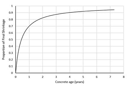
Figure 1: Concrete shrinkage over time
Figure 1 illustrates the progression of shrinkage strain over time. This curve is computed from ACI 209.2R-08 and is based on the ACI 209.2R-92 model. Note that this is unique for each concrete mix and varies with several parameters. This figure is for illustrative purposes only.
Building Code Requirements
For the design of concrete structures using the equations and prescriptive limits imposed by the building code, the objective is primarily the protection of life-safety. But code-based designs also address serviceability so that structures are durable and remain usable for their intended design life. Chapter 24 of ACI 318-19 – Building Code Requirements for Structural Concrete contains provisions for the design of structures so that they maintain serviceability.
Ground-bearing structural slabs must exceed the minimum reinforcing requirements to control cracking due to shrinkage and temperature effects. Understandably, the minimum reinforcing ratio is often specified by the design professional if it exceeds that which is otherwise required for strength. However, if HCAs are used as the primary waterproofing system, it is important that the designer minimize crack width, and, if necessary, introduce modifications to the concrete mix or increase the reinforcing quantities so that the maximum crack width is reduced to a size that can self-heal.
The problem is that restrained shrinkage crack widths are not estimated by calculation in conventional structural concrete design, and this is not required by the building codes. Furthermore, there is currently no simple method available for design professionals to estimate restrained shrinkage crack widths.
Section 24.4 of ACI 318 contains a cautionary note in the commentary that appears alongside the general provisions. Section R24.4.2, under Section 24.4 – Shrinkage and Temperature Reinforcement, states that:
‘when walls or columns provide significant restraint to shrinkage and temperature movements, […] it may be necessary to increase the amount of slab reinforcement […] in both principal directions’
R24.4.2 references an ACI article by Gibert that offers a methodology for estimating crack width for slabs and walls subjected to restrained shrinkage. This methodology is used later in this article to illustrate the effect of reinforcing quantities on the mean crack width.
Shrinkage Restraint
In large structures such as conventionally reinforced basement parking garage slabs that are cast monolithically on the ground (without pour-back strips or other devices designed to minimize shrinkage restraint), the sheer mass of the slab and the supporting subgrade provide resistance to shrinkage and thermal contraction via friction and interlock against the ground. Integrally cast footings and grade beams provide additional restraint to shrinkage because the slab is also intermittently keyed into the supporting subgrade.
At the macro-level, say for an interior one-way slab spanning 30 feet between grade beams, as shrinkage progresses, the slab will be subjected to increasing tension until a crack forms and partially relieves this tension. Reinforcing steel that crosses the crack will need to resist all the residual tension at this location. As shrinkage continues, and if the reinforcing ratio is sufficiently high, the reinforcing will remain elastic while tension in the concrete again increases until another crack forms and partially relieves the tension. The cycle of shrinking and cracking continues until the restraining forces no longer exceed the concrete tensile strength, and the shrinkage diminishes.
If the quantity of reinforcing is below a critical value, once a crack forms, the reinforcing will yield because it does not have enough strength to resist the residual tension. If this happens, it will prevent the build-up of concrete tension elsewhere that is sufficient to crack the slab again. The result is a single wide crack that continues to widen as shrinkage continues.
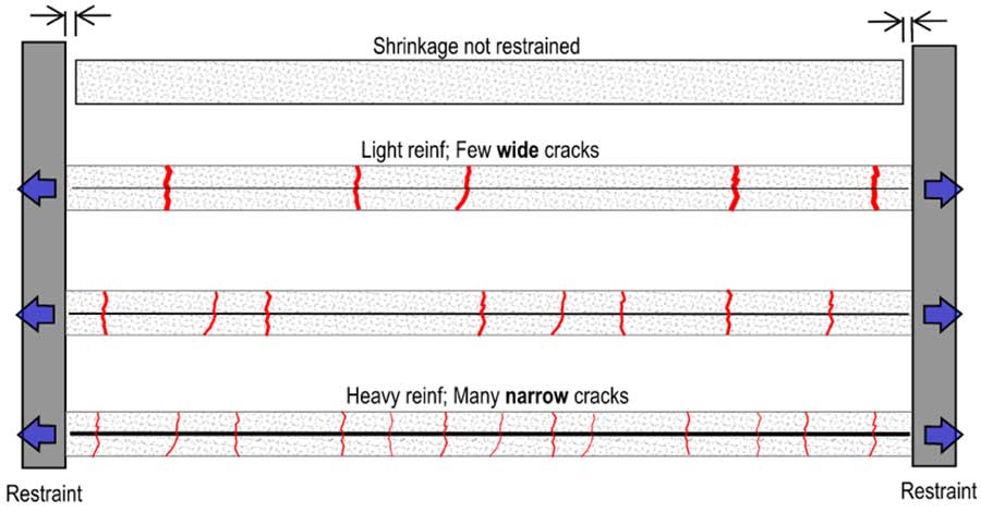
Figure 2. Shrinkage restraint cracking with increasing reinforcing ratio
Figure 2 illustrates how the pattern of slab cracks changes as the reinforcing ratio (ρ) is increased. The reinforcing ratio for a reinforced structural slab may be as little as 0.0018 (the ACI 318 minimum for a structural one-way slab) up to more than 0.01 for heavily reinforced slabs. For context, a 10-inch-thick slab with a single layer of #5 bars spaced at approximately 16 inches has a “ρ” of approximately 0.002. This is the reinforcing ratio used at the subject property for the one-way interior slabs in both the direct and perpendicular directions.
In simplest terms, when reinforcing quantities are very low, the result is a few very wide cracks. When it is high, the cracks are numerous and very narrow. As the reinforcing ratio increases, the transition between these behaviors can be quite abrupt if the ultimate shrinkage strain is in the typical range.
Crack Width Estimation
Using the methodology proposed by Gilbert, Figure 3 shows a plot of the calculated mean crack width for a concrete slab as the reinforcing ratio is increased. The slab analyzed in this case is 10 inches thick and spans 30 feet between rigid end restraints. A concrete strength of 4,000 psi is assumed. On the vertical axis is the average crack width. On the horizontal axis is the area of reinforcing expressed as a proportion of the ACI 318 minimum for shrinkage/temperature control.
For example, where As/As,min = 2, twice the ACI 318 minimum is provided. Two values of final shrinkage strain (ε*sh) were examined; one is for a typical concrete mix where ε*sh = -600 x10-6, the other is with a 25% reduction in maximum shrinkage strain where ε*sh = -450 x10-6. This lower value might be achieved with an HCA that also has shrinkage-compensating properties.

Figure 3: Estimated mean crack width for different ultimate shrinkage strains and increasing reinforcing ratio.
Figure 3 shows that for this slab, when the ACI 318 minimum reinforcing is provided (i.e., when As/As,min = 1.0), the calculated crack width is between 2 to 3 mm (~1/8-inch) because only a single crack can form. As the reinforcing ratio approaches three times the code minimum, the steel remains elastic, and the behavior changes to one where several narrower cracks occur and widths are less than 0.4 mm (0.016 inches).
Conclusion
For an HCA to provide a waterproofing system comparable to the traditional exterior membrane, it is necessary to keep the maximum anticipated restrained shrinkage crack width below the width that can self-heal. To do this, the responsible design professional should make the necessary adjustments to the concrete mix design, curing processes, and reinforcing quantities, or employ other strategies to control cracking. It should be acknowledged that the cost of simply increasing the reinforcing quantities to achieve the desired performance (i.e., not exceeding the maximum tolerable crack width) may be greater than the savings gained by opting for an HCA in lieu of a membrane.
Regarding crack width estimation, it is recommended that the methods referenced by the ACI 318 commentary be implemented with a reasonable but conservative estimate of concrete properties derived from empirical data, and that the calculated target width be somewhat less than the HCA product limit, perhaps as low as 50% to 70% of that limit. The selection of an appropriate buffer should be weighed against the functional needs of the project and the importance of achieving complete water-tightness, amongst other considerations. It is up to the specifying design professional, or the design team more broadly, to make that determination.
The key message here is that the selected reinforcing ratio, in combination with shrinkage-reducing and shrinkage-compensating admixtures and other shrinkage-controlling devices, should result in a calculated mean crack width that is less than the tolerable maximum width that the specified HCA can competently self-heal.
1 Gilbert, R. I., 1992, “Shrinkage Cracking in Fully Restrained Concrete Members,” ACI Structural Journal, V. 89 No. 2, Mar.-Apr., pp 141-149.
David Webster, PE, SE, Ph.D.,
David Webster, PE, SE, Ph.D., is principal structural engineer for building science and forensics at Jensen Hughes, a global engineering and consulting firm. Licensed as a professional engineer in Colorado, Montana, and Idaho, and as a structural engineer in Washington, Oregon, Utah, and Hawaii, David specializes in forensic structural engineering and building science applications. He can be reached at David.Webster@jensenhughes.com or 206-403-6566.
Winter 2026 Back Issue
Price range: $4.95 through $5.95
World of Concrete Preview
Deep Foundation Waterproofing: Why a Holistic Approach Matters
Polyurea Coatings: A Fast-Curing Solution for Waterproofing Concrete Decks
Beyond 6-Mil Poly: The Case for Class A Vapor Barriers
Managing Shrinkage Cracks in HCA-Waterproofed Concrete Structures
Description
Description
World of Concrete Preview
Explore waterproofing-related businesses and educational sessions at World of Concrete.
Deep Foundation Waterproofing: Why a Holistic Approach Matters
By Lisa Semling
With limited above-grade space, developers are increasingly turning to subgrade levels to house essential functions such as parking, storage, healthcare facilities, retail, and data infrastructure. But, the deeper the foundation, the more intense the challenges.
Polyurea Coatings: A Fast-Curing Solution for Waterproofing Concrete Decks
By Vanessa Salvia
Polyurea coatings offer a combination of seamless application, superior durability, and remarkably fast cure times that are changing how waterproofing projects are specified and executed.
Beyond 6-Mil Poly: The Case for Class A Vapor Barriers
By Vanessa Salvia
Moisture intrusion through concrete slabs remains one of the most challenging issues for waterproofing professionals to remedy after construction.
Managing Shrinkage Cracks in HCA-Waterproofed Concrete Structures
By David Webster, PE, SE, Ph.D
This article examines how hydrophilic crystallizing admixtures (HCAs) used as waterproofing in concrete structures require careful crack width control, as demonstrated by a Seattle building case study where inadequate reinforcing led to cracks exceeding the HCA’s self-healing capacity.
Additional Info
Additional information
| Weight | N/A |
|---|---|
| Magazine Format | Digital Download Magazine, Print Mailed Magazine |
Related products